XP95A Line Isolators ensure that all devices on an SLC remain active if an open condition exists on the circuit. In a short circuit condition, isolators isolate the shorted section between isolators to ensure the remainder of the circuit remains active
XP95A Line Isolators
Distributed Architecture
All FC-250 modules operate independently. There is no central operating system, no central point of failure. Processing power is distributed throughout the campus, increasing system survivability, eliminating home-run wiring costs while decreasing downtime due to system maintenance.
Highly Survivable
Since NAC’s and SLC’s are grouped on the same module and events are processed locally, ALM modules will perform local operations even if network communication has been severed. Distributed modules also minimize campus-wide downtime by restricting maintenance to the local module.
The Analog Loop Module (ALM3-IP) on Harding network fire controls can be wired as Style 7 (Class A) closed-loop systems. When placed on the analog loop, the line isolator module (55000-750) ensures that all devices remain active if an open condition exists on the circuit. In a short circuit condition, the entire analog circuit could potentially be disabled. By strategically placing isolators along the analog circuit, only the shorted area fault condition between isolators would be affected.
The 55000-750 uses its own unique installation base (45681-211) which will not accept any other device eliminating the possibility that any other devices could be installed in place of the isolator. The 55000-750 is compatible with XP95A and Discovery UL detector circuits.
The 45681-321 is a unique isolating base that accepts both XP95A and Discovery UL detectors – eliminating the need for traditional isolator bases at separate locations. Both XP95A and Discovery UL detectors may be mounted directly onto the 45681-321.
The ideal number of isolators is determined by the system layout with 50 isolator modules maximum on any SLC circuit. Isolators are polarity sensitive and the positive DC supply must be connected to terminal ‘L2 IN/OUT’ and the negative DC supply to terminal ‘L1 IN/OUT’.
- 55000-750 – XP95A Isolator
- 45681-211 – XP95A Isolator Base (for p/n 55000-750)
- 45681-321 – Isolator base for XP95A and Discovery UL Sensors
- Protects integrity of SLC for open and short fault conditions
- Up to 50 isolator modules per SLC
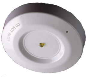
- Flashing yellow LED indicates active device
- Unique base version with restricted base does not allow insertion of any other device
- Sensor base version for use with standard XP95A and Discovery UL Sensors
- Utilizes patented sensing technique
- Self-extinguishing polycarbonate that does not fade
- Nickel-plated steel terminals for connecting a sensor
- Green/RoHS Compliant
The contractor shall furnish and install, where indicated on the plans, line isolators to protect the integrity of analog circuits. The use of isolators on an analog circuit shall ensure that all line devices remain active if an open condition exists and that short circuits will be isolated between isolators. The line isolator shall be used on analog circuits that branch off in a unique direction or to provide additional protection by isolating zone monitoring devices. The mounting base will be unique to the isolator and will not accept any other device type, or, isolating bases will be used that shall accommodate any sensor. The isolator shall contain a yellow LED that shall flash at 3 second intervals when the isolator circuit is switched on. The combination isolator and mounting base, or the isolating base shall be UL/ULC listed and UL/ULC listed as compatible with Harding network fire controls. The line isolator and base shall be Harding part numbers 55000-750 and 45681-211. The isolating bases shall be Harding part number 45681-321.
- Isolators
-
The Analog Loop Module (ALM3-IP) on Harding network fire controls can be wired as Style 7 (Class A) closed-loop systems. When placed on the analog loop, the line isolator module (55000-750) ensures that all devices remain active if an open condition exists on the circuit. In a short circuit condition, the entire analog circuit could potentially be disabled. By strategically placing isolators along the analog circuit, only the shorted area fault condition between isolators would be affected.
The 55000-750 uses its own unique installation base (45681-211) which will not accept any other device eliminating the possibility that any other devices could be installed in place of the isolator. The 55000-750 is compatible with XP95A and Discovery UL detector circuits.
The 45681-321 is a unique isolating base that accepts both XP95A and Discovery UL detectors – eliminating the need for traditional isolator bases at separate locations. Both XP95A and Discovery UL detectors may be mounted directly onto the 45681-321.
The ideal number of isolators is determined by the system layout with 50 isolator modules maximum on any SLC circuit. Isolators are polarity sensitive and the positive DC supply must be connected to terminal ‘L2 IN/OUT’ and the negative DC supply to terminal ‘L1 IN/OUT’.
- 55000-750 – XP95A Isolator
- 45681-211 – XP95A Isolator Base (for p/n 55000-750)
- 45681-321 – Isolator base for XP95A and Discovery UL Sensors
- Data Sheet
- Specs
-
- Protects integrity of SLC for open and short fault conditions
- Up to 50 isolator modules per SLC
- Flashing yellow LED indicates active device
- Unique base version with restricted base does not allow insertion of any other device
- Sensor base version for use with standard XP95A and Discovery UL Sensors
- Utilizes patented sensing technique
- Self-extinguishing polycarbonate that does not fade
- Nickel-plated steel terminals for connecting a sensor
- Green/RoHS Compliant
- Architects
-
The contractor shall furnish and install, where indicated on the plans, line isolators to protect the integrity of analog circuits. The use of isolators on an analog circuit shall ensure that all line devices remain active if an open condition exists and that short circuits will be isolated between isolators. The line isolator shall be used on analog circuits that branch off in a unique direction or to provide additional protection by isolating zone monitoring devices. The mounting base will be unique to the isolator and will not accept any other device type, or, isolating bases will be used that shall accommodate any sensor. The isolator shall contain a yellow LED that shall flash at 3 second intervals when the isolator circuit is switched on. The combination isolator and mounting base, or the isolating base shall be UL/ULC listed and UL/ULC listed as compatible with Harding network fire controls. The line isolator and base shall be Harding part numbers 55000-750 and 45681-211. The isolating bases shall be Harding part number 45681-321.